|
XT
STREAK certification tests.
Click on the download button
to initiate download of hi-resolution images.
 |
|

|
|
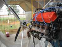
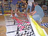
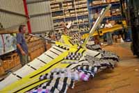
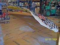
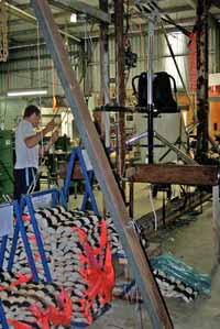
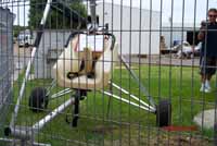
Propeller
Testing
The propeller is tested by over speed, so that in the
ultimate load test, the centrifugal forces are 2.3 times
the in service loads.
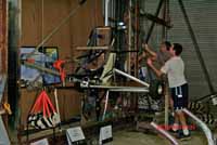
The propeller is driven by a Ford 302 Cleveland with
open carby and exhaust. Maximum power is approximately
200hp (boosted by using avgas). The propeller demonstrated
an ability to consume all of this power.
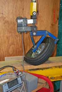
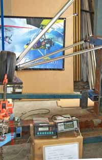
Centrifugal loading during the ultimate load test was
57220 kN (6.43tn force)
The propeller was undamaged following the test. Pictures
cannot do this test justice, with the propeller tips
operating at Mach 0.97 (320.3 m/s) and open exhaust
engine it was quite an experience as the witnesses attest
to.
Quoting Paul Mollison of AirBorne, with regard to the
limit load and ultimate load over speed testing experience:
... In the first test the noise of the unmuffled V8
was really impressive for a while but after 15 minutes
we were really happy to shut it down and give our ears
a break. For the second test the roar of the V8 faded
into the background as the prop loaded up. As we approached
the test speed the noise, the quantity of air being
moved and the vibration of the whole set up was physically
confronting. The sign to shut it down after the six
count did not need repeating. This was one severe test,
which left us in no doubt of the structural integrity
of the prop.
Les Bollenhagen of Bolly Props said
“ It was quite an experience, I can tell you.
The ground was shaking like you wouldn’t believe,
all that noise and energy tells you that it (the propeller)
is really doing something. Coming out of the test with
a propeller in perfect condition gives you an awesome
amount of confidence in your product. Following such
a successful test, all the trials and tribulations of
building the test rig, which in itself is a huge job,
are soon forgotten, and are replaced by a big smile”
The propeller and engine combination is also required
to demonstrate a safe history of operation in the aircraft.
|
|
|
|
|
|
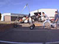
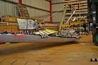
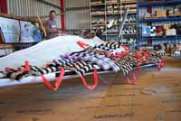
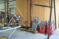
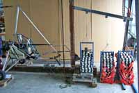
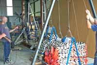
9g
forward ultimate test, emergency landing condition.
Loads applied are:
Occupant restraint, 1800 kg (3968lb)
Fuel tank 585kg (1290lb)
Oil tank 54kg (119lb)
Engine 710kg (1565lbf) applied by winch / load cell.
Following the test , the only damage was a bend of
2 degrees in the mast another bend in the shoulder
belt tang that attaches to the lap belt. This bending
is permitted in the Ultimate load test. All items
of mass were retained from simultaneous loading. Additionally
the occupant restraint was tested using the lap belts
only.
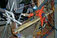
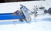
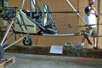
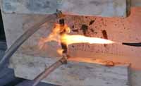
There is also a 15g forward engine restraint load
applied in a separate test, in which engine mount
loads applied are 1200kg, (2646lbf) applied by winch
/ load cell. No permanent deformation occurred. |
|
|
|
|
Our
certification policy:
AirBorne Australia has been designing and testing certified
aircraft for many years in order to operate in their
domestic market and to access other markets through
out the world. To access world markets, AirBorne have
chosen to justify the design of the Edge XT to the BCAR
S design standard. This design standard is currently
more widely accepted throughout the world than the Sport
Pilot ASTM standard. The BCAR S certification covers
a wider, more demanding range of tests so that a compliant
design requires little other work to also comply with
the Sport Pilot ASTM standard. |
|
|

 Facebook
 Youtube
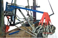